Vt Commodore Ignition Wiring Diagram, Complete Wiring Diagrams For Holden Commodore VT, VX, VY, VZ, VE, VF, 5.36 MB, 03:54, 32,796, John Amahle, 2018-08-01T19:37:41.000000Z, 19, Vt Commodore Ignition Wiring Diagram, to-ja-to-ty-to-my-to-nasz-swiat.blogspot.com, 1272 x 1800, jpeg, bcm pcm 12j swiat nasz, 20, vt-commodore-ignition-wiring-diagram, Anime Arts
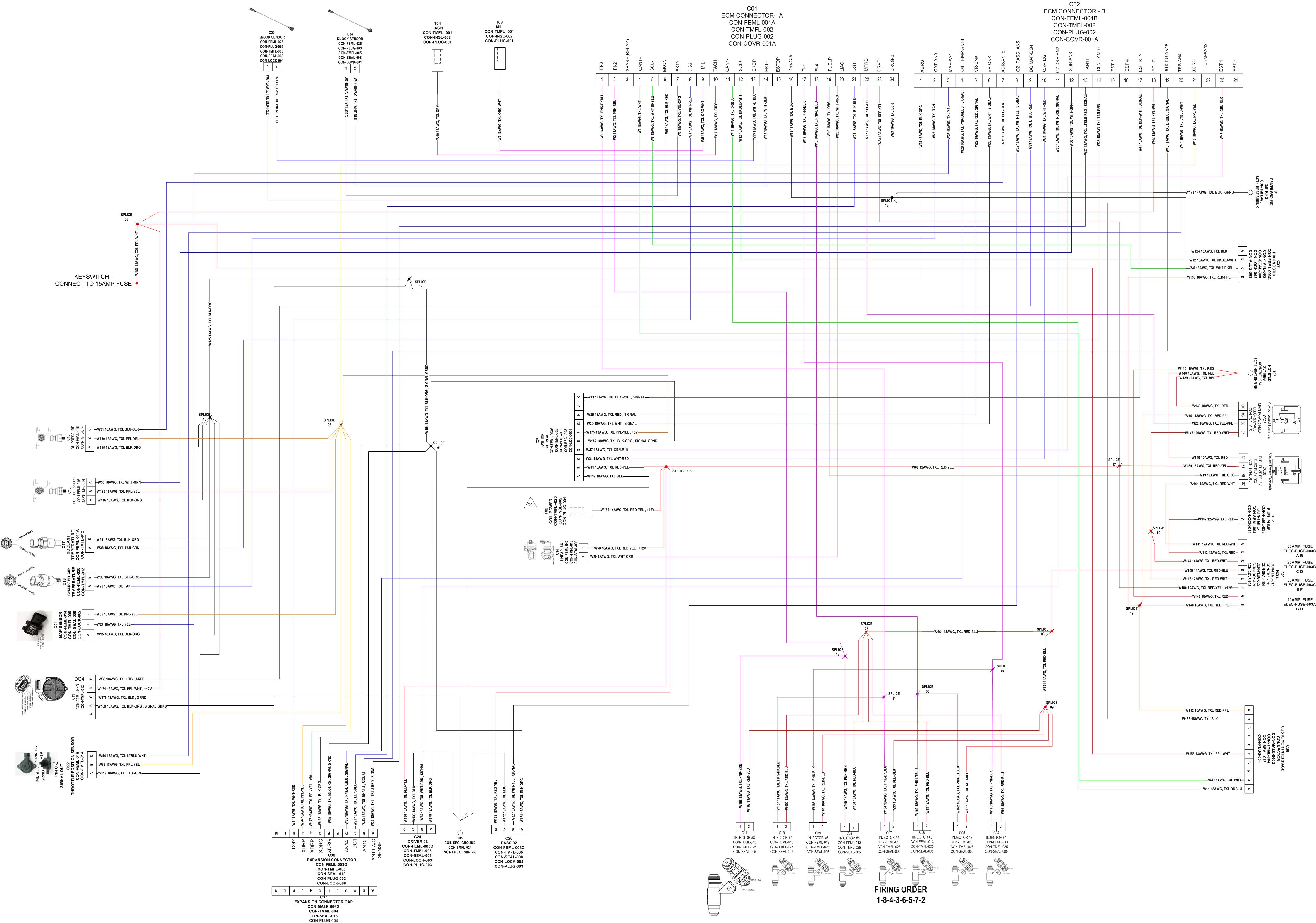
Fuel pump relay negative control side of a relay for powering a fuel pump. Do not wire directly to fuel pump. Section 3. 3 is the external wiring diagram, you should print that out. This manual contains information and diagrams related to wiring most holley efi products including ecu’s, ignition systems, nitrous systems, water/methanol injection systems, sensors, and more.
2 chang loop south croydon 3136 victoria australia. +61 3 9873 5400 fax: +61 3 9873 5955 email: 5 introduction & system requirements holley performance products has written this manual for the installation of the sniper efi tbi fuel injection system. This basic manual contains the information necessary for the installation of. This manual contains information and diagrams related to wiring most holley efi products including ecu’s, ignition systems, nitrous systems, water/methanol injection systems, sensors, and more. 3 1. 1 important wiring “do’s and don’ts. Pinout for a specific application, locate the wiring diagram themselves contained in the wiring appendix, located in the software. Crank position sensor (crank) holley efi systems work with 24x and 58x ls crank sensors.
Efi Wiring Diagram Pdf - YUMINKYO-SHOP

Wiring the FAST EZ-EFI - Infinitybox

Efi Wiring Diagram Pdf - YUMINKYO-SHOP

47 Holley Hp Efi Wiring Diagram - Wiring Diagram Source Online
e8 Wiring Diagram[1] | Fuel Injection | Electrical Connector
![Efi Wiring Diagram Pdf e8 Wiring Diagram[1] | Fuel Injection | Electrical Connector](https://imgv2-2-f.scribdassets.com/img/document/373166097/original/d64786012d/1568032158?v=1)
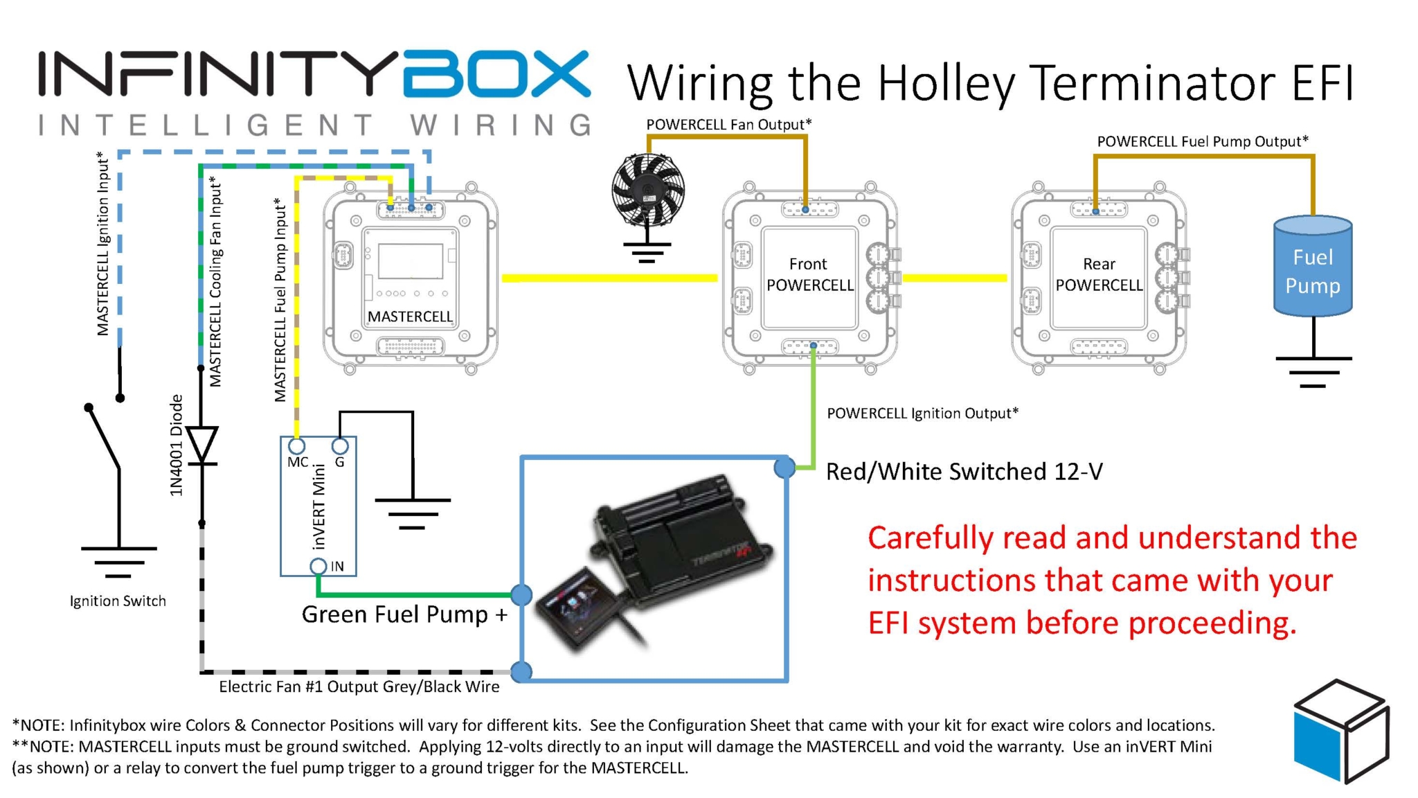
Holley Terminator EFI - Infinitybox

86 Bronco Efi Wiring Diagram

V8 flapper efi wiring diagram. Please!!! - Discovery Forum - LR4x4 - The Land Rover Forum
50 Holley Dominator Efi Wiring - Wiring Harness Diagram

[36+] Wiring Diagram Xenia Pdf
![Efi Wiring Diagram Pdf [36+] Wiring Diagram Xenia Pdf](https://static-assets.imageservice.cloud/829563/wiring-diagram-ac-mobil-avanza-new-mobil-alarm-wiring-diagram-wiring.jpg)