Vt Commodore Ignition Wiring Diagram, Complete Wiring Diagrams For Holden Commodore VT, VX, VY, VZ, VE, VF, 5.36 MB, 03:54, 32,796, John Amahle, 2018-08-01T19:37:41.000000Z, 19, Vt Commodore Ignition Wiring Diagram, to-ja-to-ty-to-my-to-nasz-swiat.blogspot.com, 1272 x 1800, jpeg, bcm pcm 12j swiat nasz, 20, vt-commodore-ignition-wiring-diagram, Anime Arts
The output will activate at the completion of the preset time (t) and will remain active until the reset signal is applied or power is interrupted. * the output is activated at the leading edge of the start signal. Timing begins on the trailing edge. Eagle signal 1/16 din timers features. One is a 30 second timer and the other a 10 second timer.
Cx100a6 from eagle signal at allied electronics. Wiring connections page 2 operation front panel page 3 control mode page 3. Timing diagrams page 7 general specifications page 8 ordering information page 8 warranty page 8 eagle signal brand. 2 to wire the unit, an 11 pin socket is required. Cx200 schematic diagrams specifications (visit www. ppe. com for additional information) voltage/frequency: Press the word signal in the eagle signal logo for 8 seconds. To disable the lock to change setpoints, remove power from the. Terminals and wiring diagram on rear of timer case danaher controls 6. 39. Wiring diagrams bold lines are internal wiring power to unit is applied to terminal 11 and 2.
Get Dayton Off Delay Timer Wiring Diagram Sample

Delay On Break Timer Wiring Diagram Download - Wiring Diagram Sample

schematics - My first PCB - How do I run signals off of the board? - Electrical Engineering

Get Dayton Off Delay Timer Wiring Diagram Sample

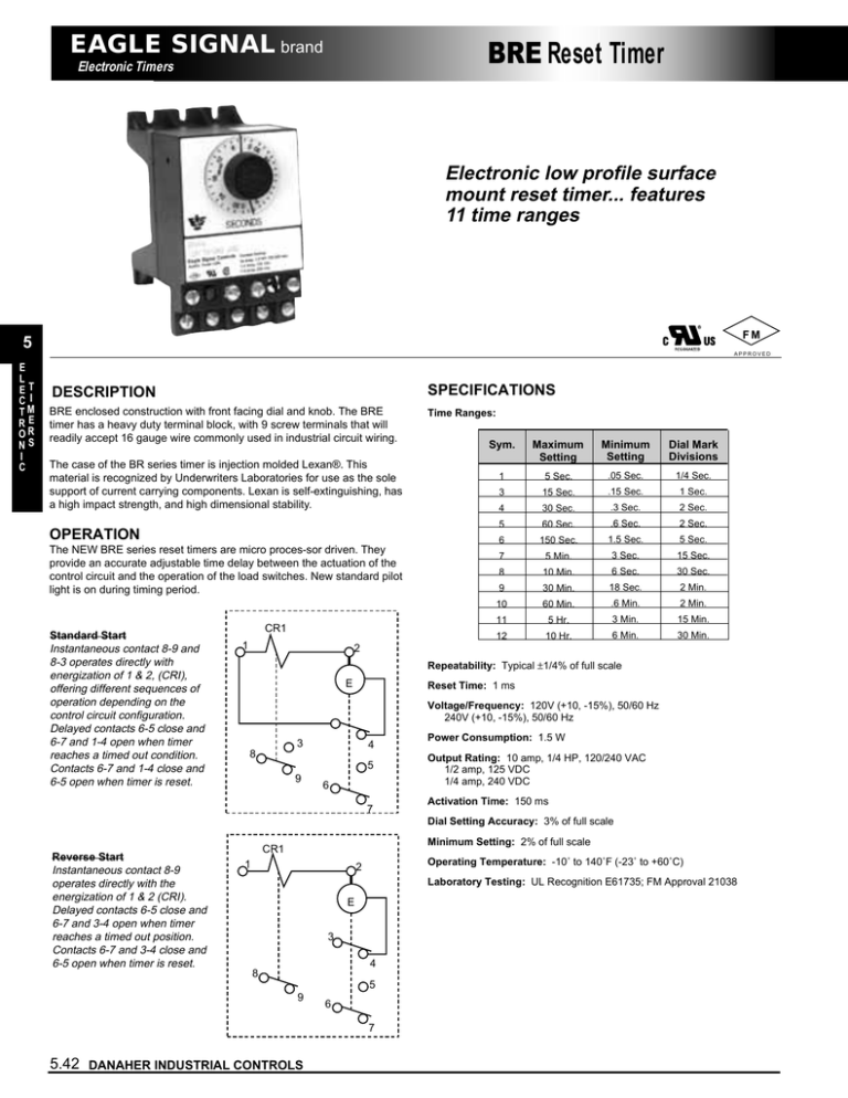
Reset Timer EAGLE SIGNAL brand 5 | Manualzz

Amy Time! Nixie Tube Clock
EAGLE WIRING DEVICES 1 – Pointer

Dayton Off Delay Timer Wiring Diagram Collection
